
He used a thermocouple bridge and voltmeter to make the measurements. Smith developed the first graphical solution in the form of a rectangular plot from his measurements of the maxima and minima voltages along the transmission line. Phillip Smith - Inventor of the Smith Chart. He relished the problem of matching the transmission line to the antenna a component he considered matched the line to space.

Although Smith did a great deal of work with antennas, his expertise and passion focused on transmission lines. In 1928, he joined Bell Labs, where he became involved in the design of antennas for commercial AM broadcasting. Smith attended Tufts College and was an active amateur radio operator with the callsign 1ANB. The Smith Chart was invented by Phillip Smith, who was born in Lexington, MA on April 29, 1905. After reading this, you will have a better understanding of impedance matching and VSWR - common parameters in a radio station. The purpose of this article is to introduce you to the basics of the Smith Chart. Visit ABOUT to see what you can learn from this blog.The Smith Chart is one of the most useful tools in radio communications, but it is often misunderstood. ‘Note: This is an article written by an RF engineer who has worked in this field for over 40 years. Let’s go on to to see a few Examples and Questions to know better about this great chart. Now you have learned all Smith chart basics and are excited to find out if you are able to use it in the RF field. \(Γ\) (gamma, reflection coefficient): the reflection coefficient is defined as the ratio between the reflected voltage wave and the incident voltage wave:.\(Z_0=R_0\), characteristic impedance, is often a real industry normalized value, such as 50Ω (RF/microwave) and 75Ω (cable), etc.1 Best power matching between source and load In order to get the best power transfer from a source to a load, the source impedance must equal the complex conjugate of the load impedance: \(Z\) (impedance, complex number, in ohms), here are 2 examples of Z:.
#Admittance smith chart how to#
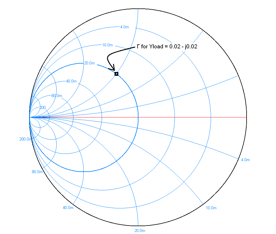
It will massively improve your RF skills if you are able to take time to learn how to use this chart. Smith chart is really just a plot of complex reflection coefficient overlaid with a normalized characteristic impedance (1 ohm) and/or admittance (1 mho or siemen) grid.Īlthough calculators and computers can now easily give answers to the problems the Smith chart was designed to solve, this great chart still remains a valuable tool. Smith chart was invented by Phillip Smith in 1939 as a graph-based method of simplifying the complex math used to describe the characteristics of RF/microwave components, and solve a variety of RF problems. What is Smith chart and how does it work? Then, we’ll show them out on Smith Chart and learn how to easily use this great chart to help you resolve those difficult RF impedance matching issues. We’ll briefly mention those basic equations that construct the Smith chart. You’ll not learn the mysteries of the Smith Chart, or those sophisticated formula and special usages of this great chart here.įirstly, you’ll learn these basic parameters such as \(Z\) (impedance), \(z\) (normalized impedance), \(Y\) (admittance), \(y\) (normalized admittance), \(R\) (real part of impedance), \(X\) (imaginary part of impedance), \(r\) (real part of normalized impedance), \(x\) (imaginary part of normalized impedance), \(G\) (real part of admittance), \(B\) (imaginary part of admittance), \(g\) (real part of normalized admittance), \(b\) (imaginary part of normalized admittance), \(Γ\) (reflection coefficient), \(VSWR\) (voltage standing wave reflection), etc. We’ll discuss the Smith Chart in this sequence and start with the very basic knowledge of this important tool that all RF people should learn and use. Impedance Matching and the Smith Chart: The Fundamentals


 0 kommentar(er)
